Components
Components to complete this tutorial are the following:
UNO
ESP 8266
Micro USB to USB cable
Generic bread board
Jumper cables (Male and Female)
Setup Your Environment
Install the Arduino IDE (Integrated development environment). This is where You can download it for Mac OS X, Windows and Linux here.
Detailed instructions can be found below:
If you are completely unfamiliar with the Arduino IDE, watch this video <a href="https://www.youtube.com/watch?v=nbD_V4QtNvY" target="_blank">here</a> to give you a better understanding of how it works.
In the Arduino IDE:
Go to menu:
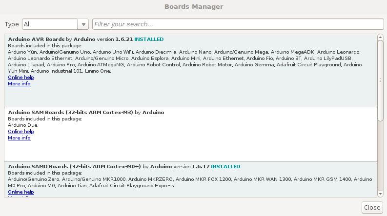
Tools > Board > Boards ManagerSearch for
Arduino AVR Boards. When found, clickInstall
Select the
Arduino\Genuino Unoboard type by going toTools > BoardSelect the port that displays
Arduino\Genuino Uno
If no name is displayed, you can find the port with the following steps:
Linux and Mac OS X
Download and install the FTDI drivers from here. Select the appropriate version for your operating system and architecture.
Open a terminal window and run the command
ls /dev/tty*Look for a device with the name that begins with
/dev/ttye.g./dev/tty.usbmodemPy343431on MAC or/dev/ttyUSB0/dev/ttyACM0on Linux.
For Linux, you may need to run the two commands below. Once you've completed that, reboot your computer. This will add permissions that will allow you to upload a sketch to the board.
sudo usermod -a -G tty ${USER} sudo usermod -a -G dialout ${USER}
Windows
Download and install the FTDI drivers from here. Select the appropriate version for your operating system and architecture.
Open the Windows start menu and search for
Device ManagerThe COM port for the Pycom device will be listed as
USB Serial Deviceor something similarKeep note of the COM port (e.g. COM4)
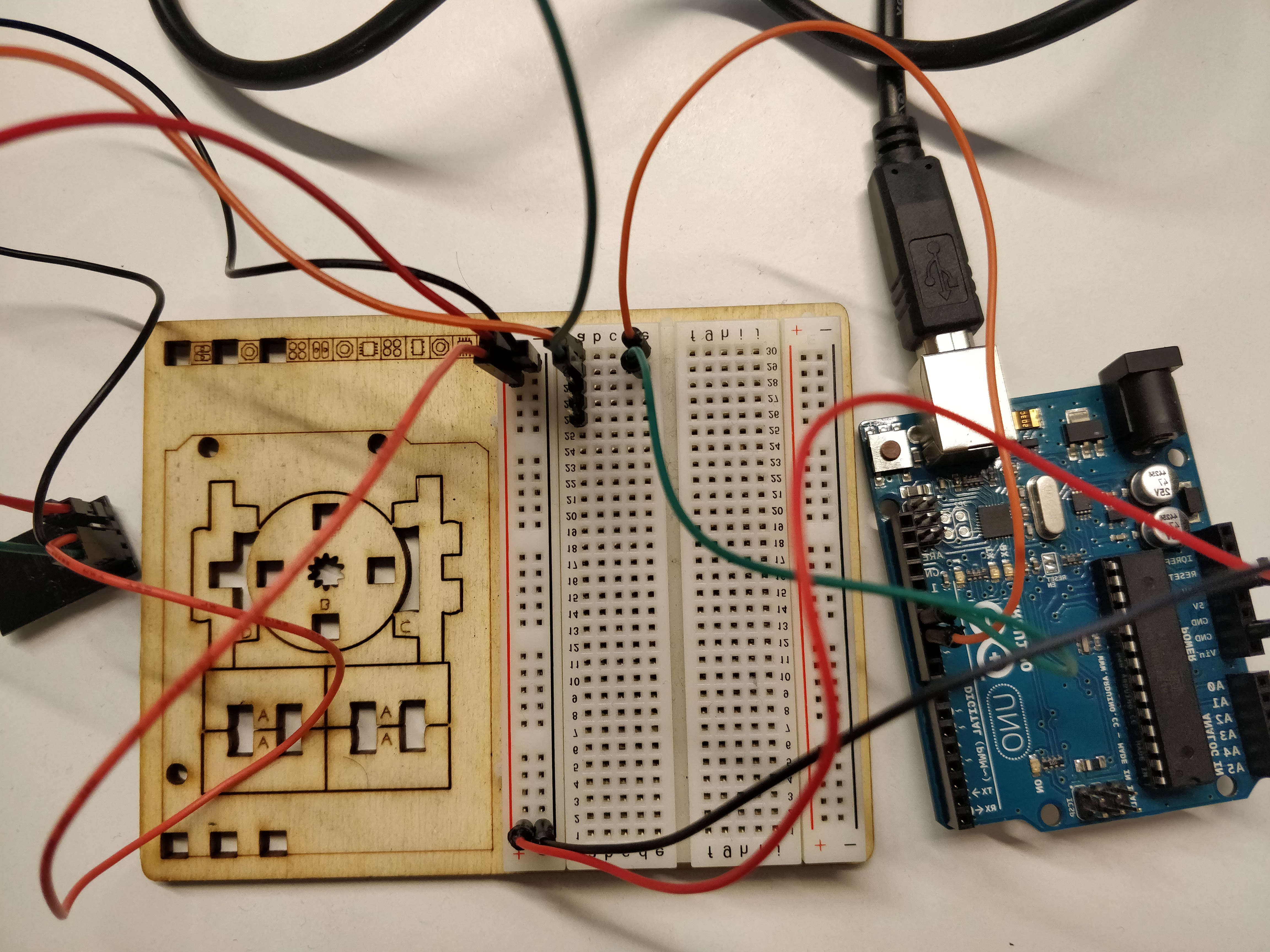
Connecting the hardware
To connect the Arduino Uno to the ESP 8266 you'll need to connect the following pins:
Arduino UNO | ESP 8266 |
|---|---|
3v3 | VCC |
GND | GND |
10 | RX |
11 | TX |
3v3 | CH_PD |
As the Ardnuino Uno takes male jumper cables while the ESP 8266 requires female jumper cable, a bread board can be used to make the connections. Its also useful as the boh the CH_PD and VCC pins on the ESP 8266 require power.
Create a new Sketch
Click on
File > Newto create a new SketchCopy and paste the publishEvent.ino or publishLocation.ino from the example code below
Add the
WIFI_SSIDandPASSWORDAdd the
device_secret_keywith your device secret key from the Wia Dashboard (the one that begins withd_sk)Sketch > Uploadto send it to your MKR GSM 1400
Go to the Wia dashboard to view the data coming through to your device.
If you need any help with getting setup or you don't understand the tutorial, tweet us, email support@wia.io or chat on Intercom.